中文
中文
 英文
英文


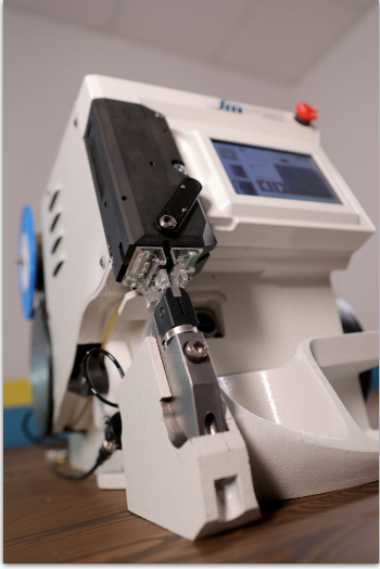
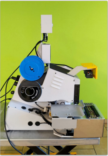
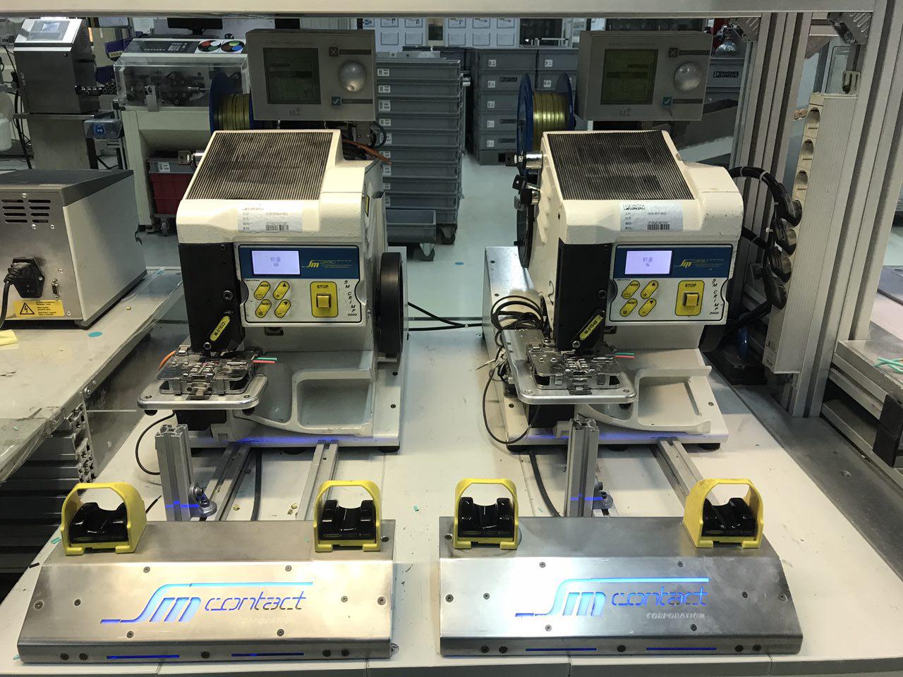
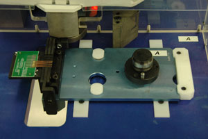
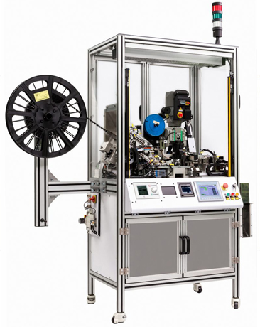
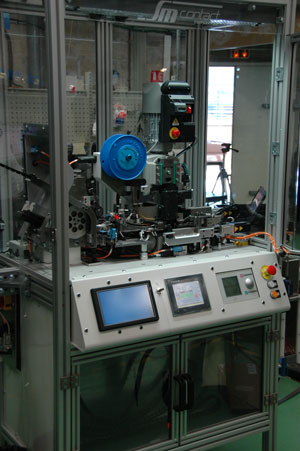
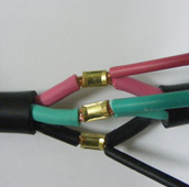
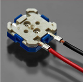
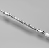
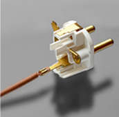
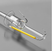
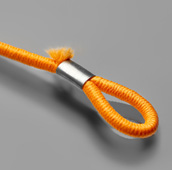
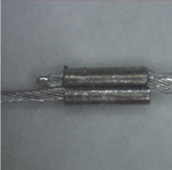
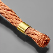
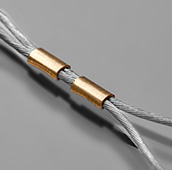
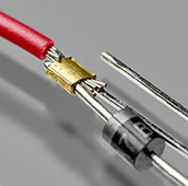
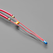
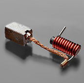
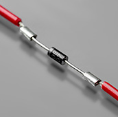
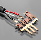
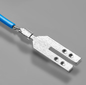
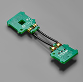
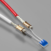
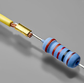
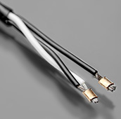
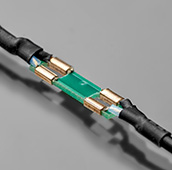
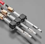
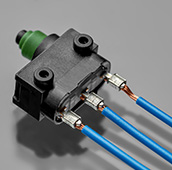
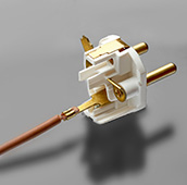
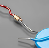
SM Contact designs and produces splice crimping machines for a wide range of electrical components: wire, PCB, coil frame, metal tab, capacitor, sensor, diode, transformer, lead frame, resistor, textile, filament, etc.
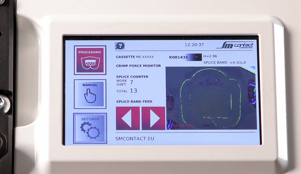
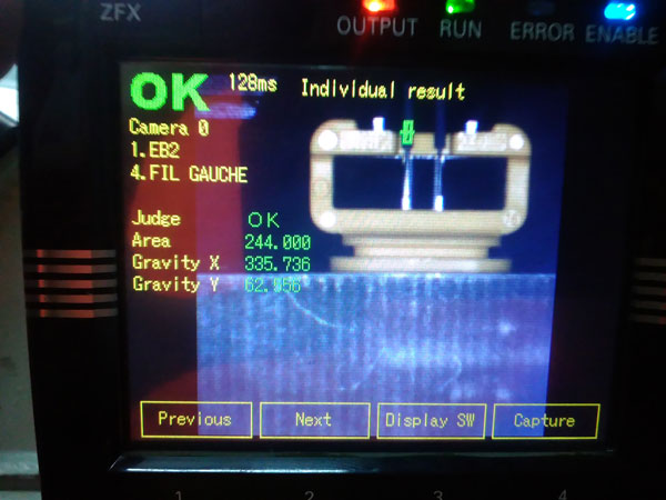
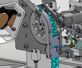
We start each project with profound connection and tooling qualification to define its optimal parameters, to adapt machine specification, and to match industry norms. Depending on the configuration, equipment performs insulation stripping, single or multiple splice crimping, inline quality control, and defective products removal.
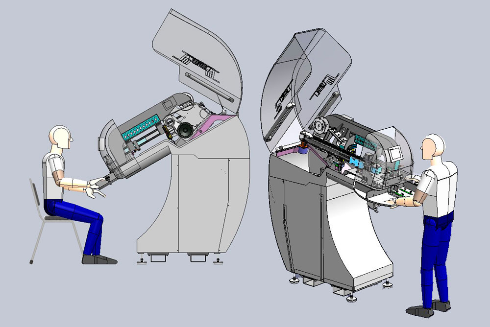
Choose one of SM Contact equipment configuration to manufacture gastight, vibration resistant, compact connection with low electrical resistance.


 +86- 20-3992 0957